Battery - Four AA batteries are used to allow more current to be supplied without the voltage droping too low. A pair of diodes are used to drop the 6V down to 5V for the microcontroller. They also preserve the charge stored in C2. The PCB allows for independent power supplies for the LED and microcontroller if desired.
Transistor base current - An emitter follower is used to boost the current to the base the transistors that switch LED current. The microcontoller is limited to about 20 mA (per pin). Q1 will boost this to several hundred mA. The base resistors are the same value because the voltage across them will be higher so the current will also be higher.
LED efficiency - The TSAL6100 LED is twice as efficient as the IR333 (on paper at least). There are also twice as many LEDs.
Programming Jumper - A jumper (JP2) is provided to turn off the LEDs so the microcontroller can be reliably reprogammed (via JP1) with new firmware.
NOTE: This design has not been built or tested. It is posted here for discussion.
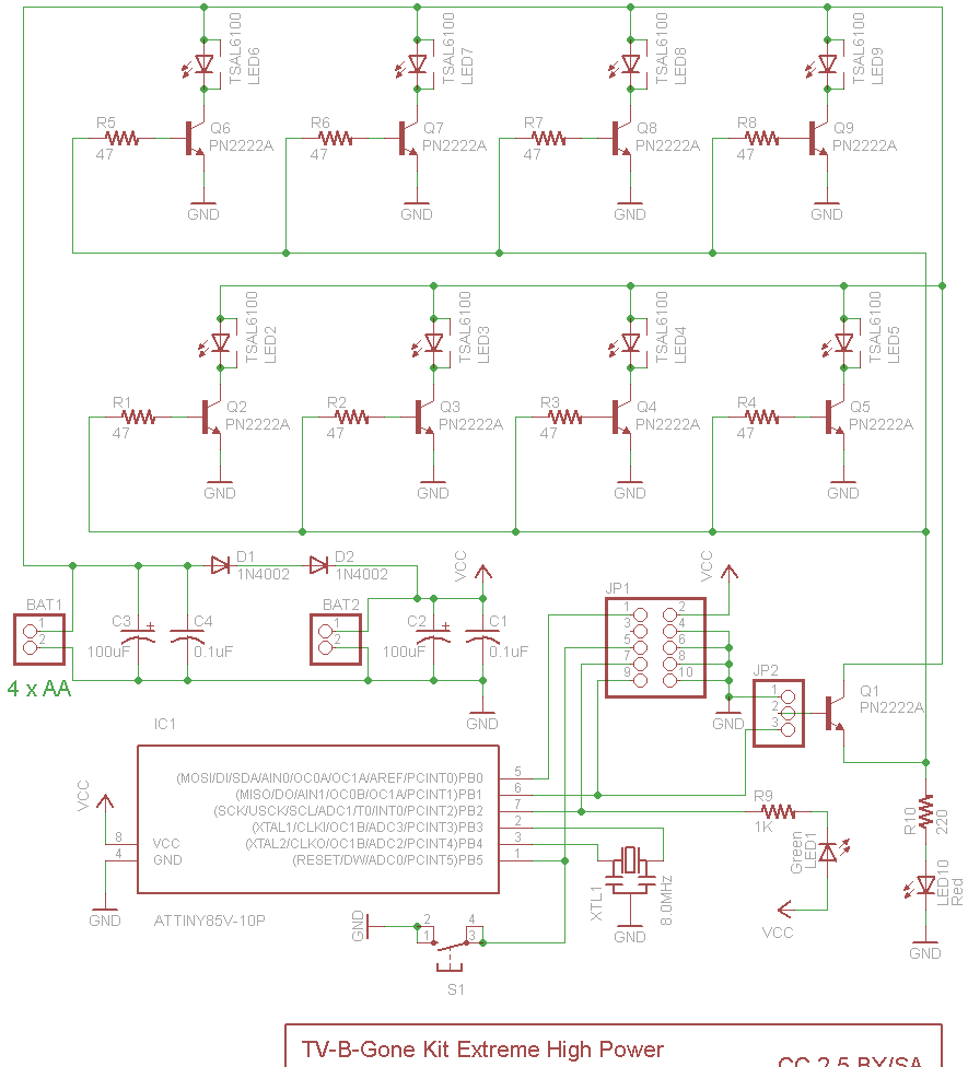
Schematic
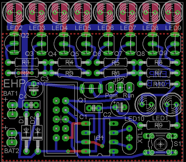
PCB