arduino PID / heating pad schematic help

Post here about your Arduino projects, get help - for Adafruit customers!

Moderators: adafruit_support_bill, adafruit

Please be positive and constructive with your questions and comments.
Locked
User avatar
ezeeetm
 
Posts: 35
Joined: Fri Oct 05, 2012 4:25 pm

arduino PID / heating pad schematic help

Post by ezeeetm »

I am an electronics/arduino newb so please bear with me.

I need to use the arduino PID library to control the output one of these 5V heating pads

https://www.sparkfun.com/products/11288

Can somebody suggest a simple schematic to accomplish this? I'm *pretty* sure I cannot drive the heating pad directly off the arduino, even though it has 5V pins...because it draws to much current. Please correct me if I'm wrong? Like I said, I'm new and the heating pad doesn't have a datasheet :(

Do I use a tiny relay or SSR? If so, what model and how would I wire it up? I would be driving this with 4 rechargeable AA batteries (~4.8V)

thanks.

User avatar
adafruit_support_bill
 
Posts: 88141
Joined: Sat Feb 07, 2009 10:11 am

Re: arduino PID / heating pad schematic help

Post by adafruit_support_bill »

Like I said, I'm new and the heating pad doesn't have a datasheet
Even experts are lost without data. You should contact Sparkfun. They should be able to help you with the technical specs of the product.

User avatar
ezeeetm
 
Posts: 35
Joined: Fri Oct 05, 2012 4:25 pm

Re: arduino PID / heating pad schematic help

Post by ezeeetm »

adafruit_support wrote:
Like I said, I'm new and the heating pad doesn't have a datasheet
Even experts are lost without data. You should contact Sparkfun. They should be able to help you with the technical specs of the product.
Just contacted them, they gave me the specs but the guy I talked to couldn't help me with the circuit advice.

he said draws .6 amps at 5V

All of my other components are adafruit (I'm only ordering this from them because you guys don't carry it)

Oh, I forgot to mention that I have a bunch of adafruit TMP36 thermistors laying around too...I was going to use those for the sensors.

User avatar
adafruit_support_bill
 
Posts: 88141
Joined: Sat Feb 07, 2009 10:11 am

Re: arduino PID / heating pad schematic help

Post by adafruit_support_bill »

0.6A at 5v should be relatively easy. One of these will handle it: http://www.adafruit.com/products/355

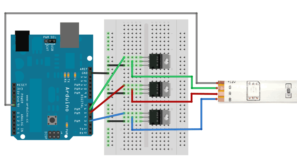
These can be driven directly from an Arduino pin. Wiring would be similar to one channel of the RGB led strips as shown here: http://www.ladyada.net/products/rgbledstrip/#usage

User avatar
ezeeetm
 
Posts: 35
Joined: Fri Oct 05, 2012 4:25 pm

Re: arduino PID / heating pad schematic help

Post by ezeeetm »

thanks, that will get me very close to a solution. I appreciate the help.

User avatar
ezeeetm
 
Posts: 35
Joined: Fri Oct 05, 2012 4:25 pm

Re: arduino PID / heating pad schematic help

Post by ezeeetm »

adafruit_support wrote: Wiring would be similar to one channel of the RGB led strips as shown here: http://www.ladyada.net/products/rgbledstrip/#usage
there are two wiring diagrams on that page...one with resistors and one without. I assume I should use the one without so the heater gets all the current it wants, right?

also, the diagram shows the LED strips hooked to the 9V on the arduino...I should hook mine to the 5V, not the 9V, correct? That is, in the image below the black wire going to 9V on the left edge of the arduino should be going to 5V..two holes above the 9V. Is this correct?

Image

User avatar
adafruit_support_bill
 
Posts: 88141
Joined: Sat Feb 07, 2009 10:11 am

Re: arduino PID / heating pad schematic help

Post by adafruit_support_bill »

there are two wiring diagrams on that page...one with resistors and one without
The one with resistors is for a different transistor. For the MOSFET suggested, you want the one without.
also, the diagram shows the LED strips hooked to the 9V on the arduino...I should hook mine to the 5V, not the 9V, correct? That is, in the image below the black wire going to 9V on the left edge of the arduino should be going to 5V..two holes above the 9V. Is this correct?
Yes and no. You do want to connect it to a 5v source. But you will likely toast your Arduino's regulator if you try to pull 0.6A from the 5v pin. Assuming you don't have any other power-hungry circuitry in this project, you should look for a regulated 5v supply rated for at least 700 mA and use that to power both the Arduino (via the 5v pin) and the heater.

This one would be a good choice: http://www.adafruit.com/products/276

User avatar
ezeeetm
 
Posts: 35
Joined: Fri Oct 05, 2012 4:25 pm

Re: arduino PID / heating pad schematic help

Post by ezeeetm »

adafruit_support wrote: you should look for a regulated 5v supply rated for at least 700 mA and use that to power both the Arduino (via the 5v pin) and the heater.
oh...this project has to be 100% battery powered (portable). I was (hoping) to run the arduino off a 9V, and run the heater off a sep bank of 4x rechargeable AA's. From OP:

"I would be driving this with 4 rechargeable AA batteries (~4.8V)"

I *think* I can figure out how to wire this like I describe above. Just so I'm clear, the mosfets are switching ground in that diagram, correct?

I'll post an image of what I think is correct before you waste any more time helping me. Thank you so much.

User avatar
ezeeetm
 
Posts: 35
Joined: Fri Oct 05, 2012 4:25 pm

Re: arduino PID / heating pad schematic help

Post by ezeeetm »

like this?

Image

User avatar
adafruit_support_bill
 
Posts: 88141
Joined: Sat Feb 07, 2009 10:11 am

Re: arduino PID / heating pad schematic help

Post by adafruit_support_bill »

A separate 4xAA supply should be fine. But you have to connect the ground to the Arduino ground also.

User avatar
ezeeetm
 
Posts: 35
Joined: Fri Oct 05, 2012 4:25 pm

Re: arduino PID / heating pad schematic help

Post by ezeeetm »

adafruit_support wrote:But you have to connect the ground to the Arduino ground also.
like this? that won't cause any issue because one ground is from a 9V source and the other is from a 5V source? I'm a little confused here...just don't want to fry my board.

everything else look ok?

Image

User avatar
adafruit_support_bill
 
Posts: 88141
Joined: Sat Feb 07, 2009 10:11 am

Re: arduino PID / heating pad schematic help

Post by adafruit_support_bill »

You need a common ground reference for your signal from pin 6. Otherwise it will not reliably switch the MOSFET. The upper end of the supply voltage is irrelevant. You won't fry anything connecting the grounds together. :D

User avatar
ezeeetm
 
Posts: 35
Joined: Fri Oct 05, 2012 4:25 pm

Re: arduino PID / heating pad schematic help

Post by ezeeetm »

adafruit_support wrote:You need a common ground reference for your signal from pin 6. Otherwise it will not reliably switch the MOSFET. The upper end of the supply voltage is irrelevant. You won't fry anything connecting the grounds together. :D
you've been very helpfu, thank you.

does the diagram in my previous post do this correctly (the red arrow)?

User avatar
adafruit_support_bill
 
Posts: 88141
Joined: Sat Feb 07, 2009 10:11 am

Re: arduino PID / heating pad schematic help

Post by adafruit_support_bill »

does the diagram in my previous post do this correctly (the red arrow)?
Yes. :D

User avatar
ezeeetm
 
Posts: 35
Joined: Fri Oct 05, 2012 4:25 pm

Re: arduino PID / heating pad schematic help

Post by ezeeetm »

adafruit_support wrote:
does the diagram in my previous post do this correctly (the red arrow)?
Yes. :D
you guys dominate the support world.

Locked
Please be positive and constructive with your questions and comments.

Return to “Arduino”