Datalogger + Thermocouple Mux
Moderators: adafruit_support_bill, adafruit
Please be positive and constructive with your questions and comments.
-
wilheldp
- Posts: 22
- Joined: Tue May 07, 2013 6:14 pm
Re: Datalogger + Thermocouple Mux
When you re-configured the TCMux code, why did you make conversionTime and intervalTime unsigned longs (4 bytes)? I changed them to ints (2 byes) because I can't imagine either of them ever needing to be over 32.7 seconds.
-
wilheldp
- Posts: 22
- Joined: Tue May 07, 2013 6:14 pm
Re: Datalogger + Thermocouple Mux
OK...I took all of your suggestions and ran the following code...
I moved...
...to various places in the code, uploaded, and monitored the SRAM. The minimum value I found was 715 bytes which occurred immediately after a logfile write. Most of the readings were 778 or 768. I then added all of the LCD stuff back in, and it dropped all the readings by exactly 32 bytes.
I only got the SD card to work once with the serial monitor open. For some reason, it very much does not like for the serial port to be initialized. Exact same code, if I reset the Arduino, the SD card initializes, makes the file, and starts logging data. When I start serial monitor, the Arduino resets, and the SD light stays on for an extended period, then the Mux select pins start cycling, but there is no datalogging. I'm not sure how I got it to work the one time it did, but that's when I saw the 715 SRAM bytes. Either way, 715 bytes leaves a lot of wiggle room.
I figured out my question above because the interval and conversion times are tied to millis(). I was confusing them with the 200ms and 2s delay timers.
Here is TEMPS00.CSV from one of the successful test runs. I think the 31.55 is just a rounding error on the conversion to Fahrenheit. When I ran the code without the LCD stuff (where the conversion takes place), I got all 0.00's for the temperature data.
Code: Select all
 //   #include <string.h> //Use the string Library
 //   #include <EEPROM.h>
 //   #include <ctype.h>
    #include <Wire.h>
  //  #include <LiquidCrystal_I2C.h>
    #include <SD.h> // SD card library
 //   #include <SPI.h>
    #include <RTClib.h>

    #define PINEN 7 //Mux Enable pin
    #define PINA0 4 //Mux Address 0 pin
    #define PINA1 5 //Mux Address 1 pin
    #define PINA2 6 //Mux Address 2 pin
    #define PINSO 12 //TCAmp Slave Out pin (MISO)
    #define PINSC 13 //TCAmp Serial Clock (SCK)
    #define PINCS 9  //TCAmp Chip Select Change this to match the position of the Chip Select Link

    //LiquidCrystal_I2C lcd(0x3F,20,4); //set the LCD address to 0x3F for a 20 chars and 4 line display
    int Temp;
    float floatTemp[8], floatInternalTemp;
    int internalTemp;
    unsigned int Mask;
    char i, channel;
    char name[] = "TEMPS00.CSV"; //File names will follow this format, and increment automatically
    unsigned long conversionTime, intervalTime;
    boolean FailGND = false;
    boolean FailSHT = false;
    boolean FailOPEN = false;
    boolean SensorFail = false;

    RTC_DS1307 RTC; // define the Real Time Clock object
    DateTime now; //define a time object "now", from the RTClib library

    // The objects to talk to the SD card
    Sd2Card card;
    SdVolume volume;
    SdFile root;
    SdFile file;
    File logfile; // The object that represents our datafile
    const byte chipSelect = 10; // chip select pin for SD card, 10 for regular Arduino, 53 for Mega

    unsigned long lastSave = 0; // time value of last save. Relies on realtime clock
    //unsigned long lcdTimeOut = 0; //timer for turning off LCD
    byte saveInterval = 10; //time between saves (units = seconds, not millis)
    //byte lcdInterval= 60; //time to wait before shutting off LCD (units = seconds)

    #define CONVERSION_TIME      200            /* number of milliseconds per conversion */
    #define CONVERSION_PERIOD   2000            /* start a new set of 8 conversions once every second */
    #define CONVERSION_INTERVAL (CONVERSION_PERIOD - (CONVERSION_TIME * 8)) /*interval between the end of a conversion cycle and the start of the next */

int freeRam() {
  extern int __heap_start,*__brkval;
  int v;
  return (int)&v - (__brkval == 0 ? (int)&__heap_start : (int) __brkval);
}
    void setup()
    {
      Serial.begin(9600);
      Wire.begin(); // You must start the Wire thing before attempting to read the real time clock
     // lcd.init();
     // lcd.backlight();
     // lcd.setCursor(0, 0);

      //initialize the SD card
      SD.begin(chipSelect);
      RTC.begin();

      // create a new file
      for (uint8_t x = 0; x < 100; x++) {
        name[5] = x/10 + '0';
        name[6] = x%10 + '0';
        if (! SD.exists(name)) {
         logfile = SD.open(name, FILE_WRITE);
         logfile.println(F("date,time,Ch1,Ch2,Ch3,Ch4,Ch5,Ch6,Ch7,Ch8")); //Write the output file header row to our file so that we can identify the data later
         logfile.flush();
         delay(100);
         break;
        }
      }


      now = RTC.now(); //update clock

      lastSave = now.unixtime(); //initialize the lastSave value so that we can
                                       //determine when to save to the SD card.
      //lcdTimeOut = now.unixtime();  //initialize lcdTimeOut to determine when to shut off the lcd backlight


      pinMode(PINEN, OUTPUT);
      pinMode(PINA0, OUTPUT);
      pinMode(PINA1, OUTPUT);
      pinMode(PINA2, OUTPUT);
      pinMode(PINSO, INPUT);
      pinMode(PINCS, OUTPUT);
      pinMode(PINSC, OUTPUT);

      digitalWrite(PINEN, HIGH);   // enable on
      digitalWrite(PINA0, LOW); // low, low, low = channel 1
      digitalWrite(PINA1, LOW);
      digitalWrite(PINA2, LOW);
      digitalWrite(PINSC, LOW); //put clock in low
      digitalWrite(PINCS, HIGH);

      channel = 0;
      selectThermocouple(channel);            //start the first conversion
      conversionTime = millis();              //timestamp start of first conversion
      intervalTime = conversionTime - CONVERSION_INTERVAL;  //back-date the start of the first conversion interval
    }

    void loop()
    {
      if (millis() > (intervalTime + CONVERSION_INTERVAL))  //start a new set of 8 conversions every CONVERSION_INTERVAL milliseconds
      {
        if (millis() > (conversionTime + CONVERSION_TIME))  //every CONVERSION_TIME milliseconds
        {
          conversionTime = millis();    //reset conversion time-out

          readThermocouple(channel);    //stop conversion and read the current thermocouple

          channel = channel + 1;  //get the next channel number

          if (channel == 8)             //if we finished all 8 conversions,
          {
            channel = 0;
            intervalTime = millis();    // reset the conversion interval time-out.
          }

          //Serial.println(channel+1,DEC);
          selectThermocouple(channel);  //select the next thermocouple and begin conversion

        } //end CONVERSION_TIME
      } //end CONVERSION _INTERVAL


  Serial.print(F("Free SRAM = "));
  Serial.println(freeRam());
      //*********************************************************************************
      //Write data to SD card if it's time to save
      now = RTC.now(); //get current time from Real Time Clock

      if (now.unixtime() >= (lastSave + saveInterval)) //if new unix time is greater than
                                                       //lastSave + saveInterval
      {
        lastSave = now.unixtime(); //update lastSave value
        logfile.print(now.month(), DEC);
        logfile.print(F("/"));
        logfile.print(now.day(), DEC);
        logfile.print(F("/"));
        logfile.print(now.year(), DEC);
        logfile.print(F(","));
        logfile.print(now.hour(), DEC);
        logfile.print(F(":"));
        logfile.print(now.minute(), DEC);
        logfile.print(F(":"));
        logfile.print(now.second(), DEC);
        logfile.print(F(","));
        //now save temperatures
        for (int i=0; i<=6;i++) { //write the first 7 temperatures in a loop
        logfile.print(floatTemp[i]);
        logfile.print(",");
        }
        logfile.println(floatTemp[7]);
        logfile.flush();
      }

    }

    void selectThermocouple(int channel)
    {
        digitalWrite(PINCS, LOW); //Take SPI bus

        switch (channel) //select channel
        {
          case 0:
            digitalWrite(PINA0, LOW);
            digitalWrite(PINA1, LOW);
            digitalWrite(PINA2, LOW);
          break;
          case 1:
            digitalWrite(PINA0, HIGH);
            digitalWrite(PINA1, LOW);
            digitalWrite(PINA2, LOW);
          break;
          case 2:
            digitalWrite(PINA0, LOW);
            digitalWrite(PINA1, HIGH);
            digitalWrite(PINA2, LOW);
          break;
          case 3:
            digitalWrite(PINA0, HIGH);
            digitalWrite(PINA1, HIGH);
            digitalWrite(PINA2, LOW);
          break;
          case 4:
            digitalWrite(PINA0, LOW);
            digitalWrite(PINA1, LOW);
            digitalWrite(PINA2, HIGH);
          break;
          case 5:
            digitalWrite(PINA0, HIGH);
            digitalWrite(PINA1, LOW);
            digitalWrite(PINA2, HIGH);
          break;
          case 6:
            digitalWrite(PINA0, LOW);
            digitalWrite(PINA1, HIGH);
            digitalWrite(PINA2, HIGH);
          break;
          case 7:
            digitalWrite(PINA0, HIGH);
            digitalWrite(PINA1, HIGH);
            digitalWrite(PINA2, HIGH);
          break;
          default:
          //  lcd.setCursor(0, 0);
          //  lcd.print(F("invalid channel: ")); lcd.println(channel);
            break;
        }

        delay(5);                  //allow for leisurely digestion
        digitalWrite(PINCS, HIGH); //Release SPI bus; Begin conversion
    }

    float readThermocouple(int channel)
    {

        Temp = 0;
        floatTemp[channel] = 0;
        internalTemp = 0;
        FailGND = false;
        FailSHT = false;
        FailOPEN = false;
        SensorFail = false;

        digitalWrite(PINCS, LOW); //Take SPI bus, stop conversion

        for (i=31;i>=0;i--)
        {
            digitalWrite(PINSC, HIGH);
            delay(1);

          if ((i<=31) && (i>=18))
          {
            // these 14 bits are the thermocouple temperature data
            // bit 31 sign
            // bit 30 MSB = 2^10
            // bit 18 LSB = 2^-2 (0.25 degC)

            Mask = 1<<(i-18);
            if (digitalRead(PINSO)==1)
            {
              if (i == 31)
              {
                Temp += (0b11<<14);//pad the temp with the bit 31 value so we can read negative values correctly
              }
              Temp += Mask;
              //Serial.print("1");
            }
            else
            {
             // Serial.print("0");
            }
          }
          //bit 17 is reserved
          //bit 16 is sensor fault
          if (i==16)
          {
            SensorFail == digitalRead(PINSO);
          }

          if ((i<=15) && (i>=4))
          {
            //these 12 bits are the internal temp of the chip
            //bit 15 sign
            //bit 14 MSB = 2^6
            //bit 4 LSB = 2^-4 (0.0625 degC)
            Mask = 1<<(i-4);
            if (digitalRead(PINSO)==1)
            {
              if (i == 15)
              {
                internalTemp += (0b1111<<12);//pad the temp with the bit 31 value so we can read negative values correctly
              }

              internalTemp += Mask;//should probably pad the temp with the bit 15 value so we can read negative values correctly
              //Serial.print("1");
            }
            else
            {
             // Serial.print("0");
            }

          }
          //bit 3 is reserved
          if (i==2)
          {
            FailSHT == digitalRead(PINSO)<<2;//bit 2 is set if shorted to VCC
          }
          if (i==1)
          {
            FailGND == digitalRead(PINSO)<<1;//bit 1 is set if shorted to GND
          }
          if (i==0)
          {
            FailOPEN == digitalRead(PINSO)<<0;//bit 0 is set if open circuit
          }


          digitalWrite(PINSC, LOW);
          delay(1);
          //delay(1);
        }

        digitalWrite(PINCS, HIGH); //Release SPI bus

       /* if (channel <= 3) lcd.setCursor(0,channel);
          else lcd.setCursor(10,channel-4);

          lcd.print(F("Cn"));
          lcd.print(channel+1);
          lcd.print(F(": "));

          if (SensorFail)
          {
            if (FailSHT)
            {
              lcd.print(F("VCC"));
            }
            if (FailGND)
            {
              lcd.print(F("GND"));
            }
            if (FailOPEN)
            {
              if (channel == 7)
              {
                lcd.setCursor(10,3);
                lcd.print(F("Int: "));
                floatInternalTemp = (float)internalTemp * 0.0625;
                floatInternalTemp = ((9 * floatInternalTemp) / 5) + 32;  //convert to Fahrenheit.
                lcd.print(floatInternalTemp,1); // If Channel 8 isn't hooked up, replace it with the internal temp
              }
              else
              {
                lcd.print(F("OPEN"));
              }
            }
          }
          else
          {
            floatTemp[channel] = (float)Temp * 0.25;
            floatTemp[channel] = ((9 * floatTemp[channel]) / 5) + 32;  //convert to Fahrenheit.
            lcd.print(floatTemp[channel],1);
          } */

      return floatTemp[channel];

    }
Code: Select all
 Serial.print(F("Free SRAM = "));
Serial.println(freeRam());I only got the SD card to work once with the serial monitor open. For some reason, it very much does not like for the serial port to be initialized. Exact same code, if I reset the Arduino, the SD card initializes, makes the file, and starts logging data. When I start serial monitor, the Arduino resets, and the SD light stays on for an extended period, then the Mux select pins start cycling, but there is no datalogging. I'm not sure how I got it to work the one time it did, but that's when I saw the 715 SRAM bytes. Either way, 715 bytes leaves a lot of wiggle room.
I figured out my question above because the interval and conversion times are tied to millis(). I was confusing them with the 200ms and 2s delay timers.
Here is TEMPS00.CSV from one of the successful test runs. I think the 31.55 is just a rounding error on the conversion to Fahrenheit. When I ran the code without the LCD stuff (where the conversion takes place), I got all 0.00's for the temperature data.
Code: Select all
date,time,Ch1,Ch2,Ch3,Ch4,Ch5,Ch6,Ch7,Ch8
6/10/2013,17:23:8,32.00,32.00,31.55,31.55,31.55,31.55,31.55,31.55
6/10/2013,17:23:18,32.00,32.00,31.55,31.55,31.55,31.55,31.55,31.55
6/10/2013,17:23:28,32.00,32.00,31.55,31.55,31.55,31.55,31.55,31.55
6/10/2013,17:23:38,32.00,32.00,31.55,31.55,32.00,31.55,31.55,31.55
6/10/2013,17:23:48,32.00,32.00,31.55,31.55,32.00,31.55,31.55,31.55
6/10/2013,17:23:58,32.00,32.00,31.55,31.55,31.55,31.55,31.55,31.55
6/10/2013,17:24:8,32.00,32.00,31.55,31.55,31.55,31.55,31.55,31.55
6/10/2013,17:24:18,32.00,32.00,31.55,31.55,31.55,31.55,31.55,31.55
6/10/2013,17:24:28,32.00,32.00,31.55,31.55,31.55,31.55,31.55,31.55-
adafruit_support_rick
- Posts: 35092
- Joined: Tue Mar 15, 2011 11:42 am

Re: Datalogger + Thermocouple Mux
All right. You win. It's not SRAM.
I don't know what it is. Time for wild guesses.
Is it possible that you have some sort of short between pins 9 and 10? Blob of solder or something?
Maybe try reconfiguring the MUX board to use pin 8 as chip-select?
Another thought is that, even though the MUX is not selected, the activity on the SPI lines is somehow affecting it.
Pin 7 is PINEN, the MUX enable pin. You might try disabling the MUX while you write to the SD card:
if (now.unixtime() >= (lastSave + saveInterval)) //if new unix time is greater than
//lastSave + saveInterval
{
digitalWrite(PINEN, LOW); // MUX enable off
lastSave = now.unixtime(); //update lastSave value
logfile.print(now.month(), DEC);
logfile.print(F("/"));
logfile.print(now.day(), DEC);
logfile.print(F("/"));
logfile.print(now.year(), DEC);
logfile.print(F(","));
logfile.print(now.hour(), DEC);
logfile.print(F(":"));
logfile.print(now.minute(), DEC);
logfile.print(F(":"));
logfile.print(now.second(), DEC);
logfile.print(F(","));
//now save temperatures
for (int i=0; i<=6;i++) { //write the first 7 temperatures in a loop
logfile.print(floatTemp);
logfile.print(",");
}
logfile.println(floatTemp[7]);
logfile.flush();
digitalWrite(PINEN, HIGH); // MUX enable on
}
-
wilheldp
- Posts: 22
- Joined: Tue May 07, 2013 6:14 pm
Re: Datalogger + Thermocouple Mux
I don't count anything as a win until it works. I am relieved that it isn't SRAM, though, because I have some ideas for a UI that are going to be variable intensive.
I checked continuity between pins 9 and 10, and got an open circuit...no short. Out of curiosity, I went ahead and changed the Mux to pin 8, but it didn't help. I tried turning the pin enable off during SD writing...no dice.
I did some probing around before checking the chip select. Here's what I found...
Running the standard TCMuxV3 code. Ch1 = pin9, Ch2 = pin12

Running my Datalogger code. Ch1 = pin9, Ch2 = pin12

Running my Datalogger code. Ch1 = pin10, Ch2 = pin12

As you can see, I get valid SPI data on the MISO pin from the Mux when running their example sketch, and pin9 is held low for ~78ms during a read. Running my datalogger code, I get no data on MISO from the Mux, and there a ~6ms low pulse on pin9 after a 65ms low pulse. I have no idea if that SD data is reasonable, but I guess it is since that is a successful addition to the logfile in the captured waveform.
I checked continuity between pins 9 and 10, and got an open circuit...no short. Out of curiosity, I went ahead and changed the Mux to pin 8, but it didn't help. I tried turning the pin enable off during SD writing...no dice.
I did some probing around before checking the chip select. Here's what I found...
Running the standard TCMuxV3 code. Ch1 = pin9, Ch2 = pin12
Running my Datalogger code. Ch1 = pin9, Ch2 = pin12
Running my Datalogger code. Ch1 = pin10, Ch2 = pin12
As you can see, I get valid SPI data on the MISO pin from the Mux when running their example sketch, and pin9 is held low for ~78ms during a read. Running my datalogger code, I get no data on MISO from the Mux, and there a ~6ms low pulse on pin9 after a 65ms low pulse. I have no idea if that SD data is reasonable, but I guess it is since that is a successful addition to the logfile in the captured waveform.
-
adafruit_support_rick
- Posts: 35092
- Joined: Tue Mar 15, 2011 11:42 am
Re: Datalogger + Thermocouple Mux
Since you've got a scope, how about a sanity check on pins 9 and 10? The two chip selects should never be low at the same time.
-
wilheldp
- Posts: 22
- Joined: Tue May 07, 2013 6:14 pm
Re: Datalogger + Thermocouple Mux
I'll get those screen captures when I get home, and I also want to see what is happening on pin 13 since the SCK is taken high while reading the Mux and back low again after it's done.
I've finally learned enough about how this stuff works to understand Mike's first post in this thread. I looked through SD.cpp, and found this...
Do you think it would work to initialize the SD card with SD.begin(10,11,0,1);? I'm not using standard serial for anything, so I don't need RXD or TXD. If that conflicts, though, I have digital pins 2, 3, and 9 and analog pins 0-3 open. I'm going to leave the TCMux CS on pin 8 since I don't want to keep resoldering the link.
EDIT: Nevermind. I suddenly realized that the datalogger shield is wired to use 11, 12, and 13 for SPI, so just changing the setup won't work without a different PCB.
I've finally learned enough about how this stuff works to understand Mike's first post in this thread. I looked through SD.cpp, and found this...
Code: Select all
boolean SDClass::begin(uint8_t csPin, int8_t mosi, int8_t miso, int8_t sck) {
  /*

    Performs the initialisation required by the sdfatlib library.

    Return true if initialization succeeds, false otherwise.

   */
  return card.init(SPI_HALF_SPEED, csPin, mosi, miso, sck) &&
         volume.init(card) &&
         root.openRoot(volume);
}
EDIT: Nevermind. I suddenly realized that the datalogger shield is wired to use 11, 12, and 13 for SPI, so just changing the setup won't work without a different PCB.
-
wilheldp
- Posts: 22
- Joined: Tue May 07, 2013 6:14 pm
Re: Datalogger + Thermocouple Mux
Here we go.
First the SCK vs. MuxCS on the TCMuxV3 sketch...
And SCK vs. MuxCS on the Datalogger sketch...
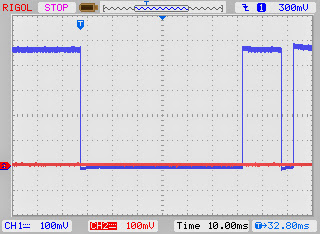
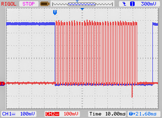
Here are three captures from the Datalogger sketch with Channel 1 on pin8 (Mux CS) and Channel 2 on pin10 (SD CS). There seemed to be 4 or 5 repeated patterns of where the SD would write in relation to the Mux read. The first capture shows one instance where the SD CS is low and it seems to prevent a the Mux CS from going low, skipping a regularly scheduled read. I never saw them low at the same time, but the last two captures are the closest they came. On the zoomed in view, you can see that the rising edge of pin10 crosses the falling edge of pin8.


First the SCK vs. MuxCS on the TCMuxV3 sketch...
And SCK vs. MuxCS on the Datalogger sketch...
Here are three captures from the Datalogger sketch with Channel 1 on pin8 (Mux CS) and Channel 2 on pin10 (SD CS). There seemed to be 4 or 5 repeated patterns of where the SD would write in relation to the Mux read. The first capture shows one instance where the SD CS is low and it seems to prevent a the Mux CS from going low, skipping a regularly scheduled read. I never saw them low at the same time, but the last two captures are the closest they came. On the zoomed in view, you can see that the rising edge of pin10 crosses the falling edge of pin8.
-
wilheldp
- Posts: 22
- Joined: Tue May 07, 2013 6:14 pm
Re: Datalogger + Thermocouple Mux
So I emailed the tech guy at Ocean Controls, directed him to this thread, and he fixed the problem on his first try.
The smoking gun, you ask? Change SD.begin(chipSelect); to SD.begin(chipSelect, 11, 12, 13);. It was already using the standard Arduino MOSI, MISO, and SCK pins, but just telling it that it had to use those pins allowed the mux to control the SCK pin (which is what tipped the Ocean guy to the real problem).
Thank you again for all your hard work on my problem, Rick. And if you're checking this thread again, thanks again to you, Greg from Ocean!
Code: Select all
date,time,Ch1,Ch2,Ch3,Ch4,Ch5,Ch6,Ch7,Ch8
6/12/2013,22:52:52,77.45,76.10,77.45,76.10,77.00,76.10,76.10,75.20
6/12/2013,22:53:2,77.45,75.65,77.45,76.10,77.00,76.10,75.65,75.20
6/12/2013,22:53:12,77.45,76.10,77.45,76.10,77.00,75.65,75.65,75.20
6/12/2013,22:53:22,93.20,76.10,77.45,76.55,77.00,76.10,77.00,75.65
6/12/2013,22:53:32,83.30,77.00,93.65,78.80,77.00,76.55,78.80,77.00
6/12/2013,22:53:42,78.80,93.65,80.60,79.70,77.00,76.55,86.90,76.10
6/12/2013,22:53:52,78.35,80.15,77.90,94.10,77.00,77.00,81.95,76.55
6/12/2013,22:54:2,78.35,77.00,76.55,81.05,77.45,77.00,94.10,76.55
6/12/2013,22:54:12,78.35,76.10,76.10,77.45,77.45,77.00,80.60,93.65Thank you again for all your hard work on my problem, Rick. And if you're checking this thread again, thanks again to you, Greg from Ocean!
-
adafruit_support_rick
- Posts: 35092
- Joined: Tue Mar 15, 2011 11:42 am
Re: Datalogger + Thermocouple Mux
Wow - I don't know if I would ever have figured that out. I went through the SD library, and now I see what's going on.
By explicitly identifying those pins, you are disabling hardware SPI. That means that the hardware is no longer in control of SCK, which allows the Ocean Controls subroutine to twiddle SCK and programmatically bit-bang the input data.
Interesting - Next time this comes up, I'll know that you can't mix hardware SPI and bit-banging on the same pins. Thanks!
-
PowderedToastMan
- Posts: 3
- Joined: Thu Jun 13, 2013 10:45 am
Re: Datalogger + Thermocouple Mux
Wow! What a timely thread!
I've been searching for a while on the best way to obtain/build a datalogger capable of Type-K TC measurements for a couple months. I came across this thread once before, but it wasn't quite so well developed then. To your credit, Rick, Wilheldp, and Greg from Ocean, I think your determination has now made the Aruino UNOr3 + Ocean Controls + DL shield the most flexible and affordable thermocouple data logger out there! I am super duper pumped to start on one of these, and hopefully I can get it all together within the next month's worth of weekends.
Just so I contributed something, here are the other "systems" I was trying to piece together:
Arduino + Thermocouple Amplifier MAX31855 for each TC + DL Shield:
http://www.adafruit.com/products/269
Arduino + AD595 Thermocouple amplifier + ADG407 multiplexer + 20x4 LCD + DL Shield + custom PCB as developed by Luke Miller:
http://lukemiller.org/index.php/2010/08 ... -platform/
A possible build (resurrection?) of the homeroasters.org TC4C Arduino based thermocouple data logger (lots of code available on link):
https://code.google.com/p/tc4-shield/
So those are all the available efforts by others. The reasons I like the system you fellas developed over these others: most affordable, least amount of part sourcing, cold junction compensated TCs (via Ocean Controls), still has 8 TC inputs.
I'm moving states this week, but I'm planning on putting the order into Ocean Controls and Adafruit when I settle at my new place. I hope this thread stays alive, because I may add my modifications, and more than likely, I'll get lost in the process. I plan on using this setup for my smoker, sous vide cooking, a coffee roaster, and doing some bench-scale thermal experiments for my job on the cheap.
Anyways, this post is getting awful long, so thanks again for putting this effort on a forum! I can't wait to get started.
-
adafruit_support_rick
- Posts: 35092
- Joined: Tue Mar 15, 2011 11:42 am
Re: Datalogger + Thermocouple Mux
Make sure you check out our new Sous-Vide cooker kit, the SousViduino!PowderedToastMan wrote:I plan on using this setup for my smoker, sous vide cooking, a coffee roaster, and doing some bench-scale thermal experiments for my job on the cheap.
http://www.adafruit.com/products/1401
-
PowderedToastMan
- Posts: 3
- Joined: Thu Jun 13, 2013 10:45 am
Re: Datalogger + Thermocouple Mux
Sweet! Thanks Rick! I really thought I scoured every corner of the Adafruit store. I wonder if I'm missing more. I think the Adafruit kits are great. Maybe they should make more...
-
wilheldp
- Posts: 22
- Joined: Tue May 07, 2013 6:14 pm
Re: Datalogger + Thermocouple Mux
Once I'm done with the UI and everything, I'll post up the entire sketch and BOM that I used for this project. This was probably WAY above my head when I started, but thanks to the patience of Rick and Greg, I've learned a ton. I'm more than willing to pay it forward and help anybody that can learn from my mistakes.
-
PowderedToastMan
- Posts: 3
- Joined: Thu Jun 13, 2013 10:45 am
Re: Datalogger + Thermocouple Mux
That sounds great. I'm about to make an order. Finally moved into a new house and dug out the hobby stuff  . Really looking forward to this one.
-
christopherb2
- Posts: 4
- Joined: Fri Jun 28, 2013 1:53 pm

Re: Datalogger + Thermocouple Mux
1.) How do you start a new post? Can't find any button.
2.)Why are some of your tutorial pages jumbled up and unreadable.
3.)I tried to download the temp/light sketch and I get the merry runaround from one page to another back to the datalogger start page?
4.)The other page adasomething or other tells me about my broswer. Why is your stuff not backwards compatible with IE.7?
Please be positive and constructive with your questions and comments.