LM2731Y outputting weird voltage

General project help for Adafruit customers

Moderators: adafruit_support_bill, adafruit

Please be positive and constructive with your questions and comments.
Locked
hxhl95
 
Posts: 10
Joined: Tue Jul 26, 2011 8:06 pm

LM2731Y outputting weird voltage

Post by hxhl95 »

Hi all,

I am making a 5V power supply using the LM2731Y chip but am getting a weird output reading of 7.5V spanning down to 5.3V. From what I can tell with a multimeter, it seems to be like a sawtooth, jumping immediately back to 7.5V after reading 5.3V. I will take some readings with a scope tomorrow.

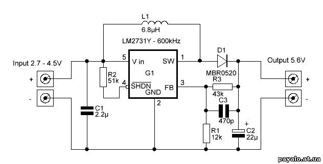
If the range were smaller I would normally attribute this to bad caps (high ESR and so on) but this doesn't seem to be merely ripple voltage. The only other thing that comes to mind is my board design. I am using all through-hole components except the inductor and the chip itself, so some of the decoupling caps are farther from the chip than I'd like. I have also used a normal electrolytic in parallel with two ceramics, whereas the datasheet recommends special, higher-quality low-ESR caps. Other than that I am using the chip exactly as the "typical application circuit" specifies, for 3.3V to 5V (with SHDN shorted to power).

Is something wrong with my board design, or does this sound like a soldering problem or something like that?

Thanks :)

User avatar
Franklin97355
 
Posts: 23940
Joined: Mon Apr 21, 2008 2:33 pm

Re: LM2731Y outputting weird voltage

Post by Franklin97355 »

Is something wrong with my board design, or does this sound like a soldering problem or something like that?
Without good pictures of the board, schematics and such how are we to tell?
Good, clear, closeup pictures will help along with the actual schematic you used to design the board.

User avatar
neutron spin
 
Posts: 163
Joined: Sat Apr 03, 2010 6:11 pm

Re: LM2731Y outputting weird voltage

Post by neutron spin »

Read the Application Hints on the data sheet and ensure you are using the correct components. These switching supplies are subject to ringing and all sorts of odd behavior is you are not using the correct filters. More info is needed...I.E. waveforms etc...I am assuming you are using the Application Note on the data sheet for 3.3Vin to 5VOUT....Also if you just need a boost supply like this you can get them cheap on E-bay for a few dollars and other places...not sure if Adafruit sells them....

hxhl95
 
Posts: 10
Joined: Tue Jul 26, 2011 8:06 pm

Re: LM2731Y outputting weird voltage

Post by hxhl95 »

This is pretty much the schematic I am following (which is also the recommend application schematic).
Image
I am using the following inductor: http://search.digikey.com/us/en/product ... -ND/956728
For the diode I am using: http://search.digikey.com/us/en/product ... ND/2075774
I have replaced R3 and R1 with 47K and 15K resistors, respectively. This gives me a 5V output according to the datasheet.
I have also shorted SHDN to power and added a few more filtering caps (two 0.1uF ceramics and a 100uF electrolytic on the output end) for stability.

From what I can tell, these substitutions should not make a large difference.

However, here are the rather odd waveforms I am getting.

Cathode of diode (i.e. output voltage):
Image

Anode of diode (i.e. SW pin):
Image

Power to chip (i.e. pins 4 and 5):
Image

Voltage at divider (i.e. FB pin):
Image

The gaps are just where the scope is scanning, I had it set on 1 second/interval to show the waveforms properly.

I have never worked with a boost converter before, but from what I can tell there seems to be an issue with my design, because I cannot find any soldering issues, I am following the schematic, and the waveforms are regular and periodic (I think malfunctions or shorts will cause noise, not odd waveforms?). However, the chip is introducing these weird, regular noises into the input voltage, which I am certain is caused by this chip: my battery circuitry is isolated from the rest of the power circuitry by a standard MOSFET controller, and it outputs a steady 3.97V without any noise.

I will try to get some good, high-quality photos tomorrow. With these waveforms and parts, can any of you experienced engineers out there spot the issue? If not, expect photos to be up by tomorrow.

User avatar
neutron spin
 
Posts: 163
Joined: Sat Apr 03, 2010 6:11 pm

Re: LM2731Y outputting weird voltage

Post by neutron spin »

Try a different inductor...it may be saturating. Does the Mfg recommend a specific type? Also try a fast recovery diode. T :) hey specify a Schottky but try one anyways....that is my 2 pennies...good luck..

hxhl95
 
Posts: 10
Joined: Tue Jul 26, 2011 8:06 pm

Re: LM2731Y outputting weird voltage

Post by hxhl95 »

I doubt the inductor is saturating given its specs, but I'll have a go at replacing it after Christmas. The diode is a fast-recovery as specified by the datasheet and Digikey. Thanks neutron spin.

Anyone out there experienced with boost converters have other suggestions? Pictures coming soon, apologies for the delay.

User avatar
neutron spin
 
Posts: 163
Joined: Sat Apr 03, 2010 6:11 pm

Re: LM2731Y outputting weird voltage

Post by neutron spin »

One more thing....if you are doing this design on a breadboard some of these switchers are very sensitive to physical design in that component placement is critical. Many require proper de-coupling or shielding from stray induced voltages. Not sure about the LM2731Y but the data sheet many times will recommend a printed circuit board design. Good luck! :)

hxhl95
 
Posts: 10
Joined: Tue Jul 26, 2011 8:06 pm

Re: LM2731Y outputting weird voltage

Post by hxhl95 »

But what if I want to use them on a through-hole board design? I can't follow the recommended PCB layout because the through-hole parts are too big. I should have breadboarded this before going ahead and making a board for it.. again, thanks for your advice, neutron spin.

Does anyone have suggestions for using boost converters with other through-hole components?

User avatar
neutron spin
 
Posts: 163
Joined: Sat Apr 03, 2010 6:11 pm

Re: LM2731Y outputting weird voltage

Post by neutron spin »

hxhl95 wrote:But what if I want to use them on a through-hole board design? I can't follow the recommended PCB layout because the through-hole parts are too big. I should have breadboarded this before going ahead and making a board for it.. again, thanks for your advice, neutron spin.

Does anyone have suggestions for using boost converters with other through-hole components?
You are quite welcome. We all have been through this at one time in doing these designs. I have many "ice scrapers" left from failed projects...I know how frustrating it can be. Just keep trying and eventually you will work it out :)

What I try to do if it is a common design I will clone part of a successful design and hope for the best. If you etch your own boards this makes it less painful on the budget. There are many books on board layout using SMPS design. It is a science all by itself...good designing and luck to boot! :D

Locked
Please be positive and constructive with your questions and comments.

Return to “General Project help”