I am working a little project and I am hoping someone can help me because I am stuck.
I am making an LED lamp that consist of 6 Common cathode RGB LEDs. I have them in parallel.
Each of the 6 Blue and Green have a 100 ohm resister and a 56 ohm for ever two of the red.
I pigtail all the Reds to Reds, Greens to Greens and Blues to Blues.
I am using 3 2N2907 PNP transistors.
I have a 330 ohm resistor on the Bases going to one of three pins on the Arduino 3/ R, 5/G 6/B.
I have the Led from the LEDs going to the Emitter and the Collector going to 5v.
I am using a color fade/transition sketch I found on the net.
The issues is this, When I run it on the Arduino WITH OUT transistors it works fine.
But when I use Transistors ( And I will need them because I am going to be moving this to an atTiny85) for some reason when it fads from Blue to green.
The blue almost fades to nothing and then the blue comes on. And the same thing from green to blue.
The video like shows what I am talking about. The first 45 sec or so is with out transistors and then after the black screen is with Transistors.
http://www.youtube.com/watch?v=on6Qf8OeYgg
Thanks for any help.
Transistor Issue
Moderators: adafruit_support_bill, adafruit
Please be positive and constructive with your questions and comments.
-
modeller
- Posts: 118
- Joined: Sat Jan 19, 2013 11:12 am

Re: Transistor Issue
I don't know, but even though you tried to explain the circuit in words, it's better to post a schematic diagram to avoid any misunderstandings. 
-
zener
- Posts: 4567
- Joined: Sat Feb 21, 2009 2:38 am

Re: Transistor Issue
I was also going to say that. But I always say that! I get tired of saying that...
Also, I have a question about this:
Also, I have a question about this:
It works fine? The lights light up and everything works?When I run it on the Arduino WITH OUT transistors it works fine.
-
adafruit_support_mike
- Posts: 67485
- Joined: Thu Feb 11, 2010 2:51 pm

Re: Transistor Issue
Are you inverting the signal that goes to the transistors?
If you have common-collector LEDs it means you're driving the anodes from the Arduino. That means the Arduino pins have to be HIGH when you want the LEDs to light up.
A PNP transistor will only allow current to flow to the LEDs when its base is LOW. Sending the Arduino's pin HIGH will turn the LEDs on if you connect them directly to the Arduino, but will turn the LEDs off if you drive them through a transistor.
-
kculm
- Posts: 35
- Joined: Sun Dec 23, 2012 7:34 pm
Re: Transistor Issue
Sorry My Bad... I am not to good at schematic thoughZener wrote:I was also going to say that. But I always say that! I get tired of saying that...
Also, I have a question about this:
It works fine? The lights light up and everything works?When I run it on the Arduino WITH OUT transistors it works fine.
And yes all the LED light up and Fade in and out nicely.
- Attachments
-
- LED-Lamp1.jpg (33.96 KiB) Viewed 6612 times
-
kculm
- Posts: 35
- Joined: Sun Dec 23, 2012 7:34 pm
Re: Transistor Issue
I should of also posted the Sketch.
Code: Select all
/*
 RGB LED - Automatic Smooth Color Cycling

 Marco Colli
 April 2012
 Uses the properties of the RGB Colour Cube
 The RGB colour space can be viewed as a cube of colour. If we assume a cube of dimension 1, then the
 coordinates of the vertices for the cubve will range from (0,0,0) to (1,1,1) (all black to all white).
 The transitions between each vertex will be a smooth colour flow and we can exploit this by using the
 path coordinates as the LED transition effect.
*/
// Output pins for PWM
#define  R_PIN  3  // Red LED
#define  G_PIN  5  // Green LED
#define  B_PIN  6  // Blue LED

// Constants for readability are better than magic numbers
// Used to adjust the limits for the LED, especially if it has a lower ON threshold
#define  MIN_RGB_VALUE  10   // no smaller than 0.
#define  MAX_RGB_VALUE  255  // no bigger than 255.

// Slowing things down we need ...
#define  TRANSITION_DELAY  70   // in milliseconds, between individual light changes
#define  WAIT_DELAY        500 // in milliseconds, at the end of each traverse
//
// Total traversal time is ((MAX_RGB_VALUE - MIN_RGB_VALUE) * TRANSITION_DELAY) + WAIT_DELAY
// eg, ((255-0)*70)+500 = 18350ms = 18.35s

// Structure to contain a 3D coordinate
typedef struct
{
  byte  x, y, z;
} coord;

static coord  v; // the current rgb coordinates (colour) being displayed

/*
 Vertices of a cube

    C+----------+G
    /|        / |
  B+---------+F |
   | |       |  |    y
   |D+-------|--+H   ^  7 z
   |/        | /     | /
  A+---------+E      +--->x

*/
const coord vertex[] =
{
 //x  y  z      name
  {0, 0, 0}, // A or 0
  {0, 1, 0}, // B or 1
  {0, 1, 1}, // C or 2
  {0, 0, 1}, // D or 3
  {1, 0, 0}, // E or 4
  {1, 1, 0}, // F or 5
  {1, 1, 1}, // G or 6
  {1, 0, 1}  // H or 7
};

/*
 A list of vertex numbers encoded 2 per byte.
 Hex digits are used as vertices 0-7 fit nicely (3 bits 000-111) and have the same visual
 representation as decimal, so bytes 0x12, 0x34 ... should be interpreted as vertex 1 to
 v2 to v3 to v4 (ie, one continuous path B to C to D to E).
*/
const byte path[] =
{
  0x01, 0x23, 0x76, 0x54, 0x03, 0x21, 0x56, 0x74,  // trace the edges
  0x13, 0x64, 0x16, 0x02, 0x75, 0x24, 0x35, 0x17, 0x25, 0x70,  // do the diagonals
};

#define  MAX_PATH_SIZE  (sizeof(path)/sizeof(path[0]))  // size of the array

void setup()
{
  pinMode(R_PIN, OUTPUT);   // sets the pins as output
  pinMode(G_PIN, OUTPUT);
  pinMode(B_PIN, OUTPUT);
}

void traverse(int dx, int dy, int dz)
// Move along the colour line from where we are to the next vertex of the cube.
// The transition is achieved by applying the 'delta' value to the coordinate.
// By definition all the coordinates will complete the transition at the same
// time as we only have one loop index.
{
  if ((dx == 0) && (dy == 0) && (dz == 0))   // no point looping if we are staying in the same spot!
    return;

  for (int i = 0; i < MAX_RGB_VALUE-MIN_RGB_VALUE; i++, v.x += dx, v.y += dy, v.z += dz)
  {
    // set the colour in the LED
    analogWrite(R_PIN, v.x);
    analogWrite(G_PIN, v.y);
    analogWrite(B_PIN, v.z);

    delay(TRANSITION_DELAY);  // wait fot the transition delay
  }

  delay(WAIT_DELAY);          // give it an extra rest at the end of the traverse
}

void loop()
{
  int    v1, v2=0;    // the new vertex and the previous one

  // initialise the place we start from as the first vertex in the array
  v.x = (vertex[v2].x ? MAX_RGB_VALUE : MIN_RGB_VALUE);
  v.y = (vertex[v2].y ? MAX_RGB_VALUE : MIN_RGB_VALUE);
  v.z = (vertex[v2].z ? MAX_RGB_VALUE : MIN_RGB_VALUE);

  // Now just loop through the path, traversing from one point to the next
  for (int i = 0; i < 2*MAX_PATH_SIZE; i++)
  {
    // !! loop index is double what the path index is as it is a nybble index !!
    v1 = v2;
    if (i&1)  // odd number is the second element and ...
      v2 = path[i>>1] & 0xf;  // ... the bottom nybble (index /2) or ...
    else      // ... even number is the first element and ...
      v2 = path[i>>1] >> 4;  // ... the top nybble

    traverse(vertex[v2].x-vertex[v1].x,
             vertex[v2].y-vertex[v1].y,
             vertex[v2].z-vertex[v1].z);
  }
}
-
adafruit_support_mike
- Posts: 67485
- Joined: Thu Feb 11, 2010 2:51 pm
Re: Transistor Issue
About that part where you have two red LEDs connected to the same resistor:

uh.. don't.
Different LEDs have different forward voltages, even when they come from the same batch. For parallel circuits, the rule is "one LED, one resistor".
uh.. don't.
Different LEDs have different forward voltages, even when they come from the same batch. For parallel circuits, the rule is "one LED, one resistor".
-
kculm
- Posts: 35
- Joined: Sun Dec 23, 2012 7:34 pm
Re: Transistor Issue
[email protected] wrote:About that part where you have two red LEDs connected to the same resistor:
uh.. don't.
Different LEDs have different forward voltages, even when they come from the same batch. For parallel circuits, the rule is "one LED, one resistor".
Being as Green as i am, I used this tool to tell me what size and layout for the resistors.
http://led.linear1.org/led.wiz
I found another sketch that works,
Code: Select all
#define RED 3
 #define GREEN 5
 #define BLUE 6
 #define delayTime 70

void setup() {

  pinMode(GREEN, OUTPUT);
   pinMode(BLUE, OUTPUT);
   pinMode(RED, OUTPUT);
   digitalWrite(GREEN, HIGH);
   digitalWrite(BLUE, HIGH);
   digitalWrite(RED, HIGH);
 }

int redVal;
 int blueVal;
 int greenVal;

 void loop() {

   int redVal = 255;
   int blueVal = 0;
   int greenVal = 0;
   for( int i = 0 ; i < 255 ; i += 1 ){
     greenVal += 1;
     redVal -= 1;
     analogWrite( GREEN, 255 - greenVal );
     analogWrite( RED, 255 - redVal );

    delay( delayTime );
   }

   redVal = 0;
   blueVal = 0;
   greenVal = 255;
   for( int i = 0 ; i < 255 ; i += 1 ){
     blueVal += 1;
     greenVal -= 1;
     analogWrite( BLUE, 255 - blueVal );
     analogWrite( GREEN, 255 - greenVal );

    delay( delayTime );
   }

   redVal = 0;
   blueVal = 255;
   greenVal = 0;
   for( int i = 0 ; i < 255 ; i += 1 ){
     redVal += 1;
     blueVal -= 1;
     analogWrite( RED, 255 - redVal );
     analogWrite( BLUE, 255 - blueVal );

    delay( delayTime );
   }
}Thanks for the Help. Its the only way I am going to learn.
Last edited by kculm on Thu Feb 21, 2013 6:06 pm, edited 1 time in total.
-
kculm
- Posts: 35
- Joined: Sun Dec 23, 2012 7:34 pm
Re: Transistor Issue
New Issue.
Like I said, I had found a new sketch that will do what I need.
Now the issue is this. I moved the sketch on to a atTiny85. and I am powering it with a Extech 80 DC switching power supply. And it works fine, nice slow and smooth transition.
But when I try to use a 5v 450 mA wall wort it start going must faster and not as smooth.
Now guys and gals, I know these are all basic question so please forgive me for asking them.
Also, if any one knows of a tutor or any club's in the West Palm Beach Area of Florida, please PM me.
Thanks
-
kculm
- Posts: 35
- Joined: Sun Dec 23, 2012 7:34 pm
Re: Transistor Issue
Think I got the second issue fixed.
I put a 120 ohm resistor form 5v to Pin 8(vcc) on the atTiny85 and all is good.
I guessed at the size. I would love to know why it worked\.
Thanks
I put a 120 ohm resistor form 5v to Pin 8(vcc) on the atTiny85 and all is good.
I guessed at the size. I would love to know why it worked\.
Thanks
-
zener
- Posts: 4567
- Joined: Sat Feb 21, 2009 2:38 am
Re: Transistor Issue
So there are 2 questions now I think:
Why did the second sketch work, and why did the series resistor help?
For the first question, did you understand mstone's first post? The answer is there. If you understand what he said, then you look at the second code, you can see a little difference that made it work. Let me know if you can find it.
As for the second question, that is a little odd. What kind of wall wart do you have? Is it a light weight regulated one, or the older heavy kind that is unregulated? Did you measure the exact voltage it puts out with a volt meter? Maybe that is the issue.
-
kculm
- Posts: 35
- Joined: Sun Dec 23, 2012 7:34 pm
Re: Transistor Issue
I thought he meant I had to set the pins High.Zener wrote:So there are 2 questions now I think:
Why did the second sketch work, and why did the series resistor help?
For the first question, did you understand mstone's first post? The answer is there. If you understand what he said, then you look at the second code, you can see a little difference that made it work. Let me know if you can find it.
light weight one for a Black Berry . Metered at 5.2vAs for the second question, that is a little odd. What kind of wall wart do you have? Is it a light weight regulated one, or the older heavy kind that is unregulated? Did you measure the exact voltage it puts out with a volt meter? Maybe that is the issue.
-
kculm
- Posts: 35
- Joined: Sun Dec 23, 2012 7:34 pm
Re: Transistor Issue
In the first sketch i changed the line of code from
#define MAX_RGB_VALUE 255
to
#define MAX_RGB_VALUE 245
and it works much better, The full RED,Blues and Green are not as rich but look OK. Now I know the real issue is not the code but something to do with the power.
#define MAX_RGB_VALUE 255
to
#define MAX_RGB_VALUE 245
and it works much better, The full RED,Blues and Green are not as rich but look OK. Now I know the real issue is not the code but something to do with the power.
-
adafruit_support_mike
- Posts: 67485
- Joined: Thu Feb 11, 2010 2:51 pm
Re: Transistor Issue
Ah.. there's an important detail: if you tell the software you want two LEDs and click the 'schematic' button, you'll see the LEDs arranged in series (cathode of the first connected to the anode of the second). That's different from putting them in parallel (single resistor connected to both anodes).kculm wrote:Being as Green as i am, I used this tool to tell me what size and layout for the resistors.
http://led.linear1.org/led.wiz
When you put the LEDs side by side (both cathodes connected to GND), you want a resistor per LED.
Depending on how much power is available, you could end up burning out one of the red LEDs. I've seen badly-connected LEDs explode in a shower of sparks before.
-
modeller
- Posts: 118
- Joined: Sat Jan 19, 2013 11:12 am
Re: Transistor Issue
Well ...
A true parallel LED connection wouldn't have one resistor per LED. It would have, as the name suggests, the LEDs wired in parallel, and only one resistor, as this -
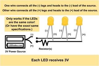
http://nuigroup.com/forums/viewthread/1030/
Wiring up one resistor per LED, then connecting each of those to a power supply, is merely (and this is slightly semantical) connecting more than one series LED circuit to share a single power supply. I wouldn't call that connecting the LEDs in parallel, I would call that connecting a few series LED circuits to a single power supply.
I don't like the true parallel connection, but it is possible, and people do it, but at the minimum, you better use the same color LED from the same manufacturer (at the minimum).
A true parallel LED connection wouldn't have one resistor per LED. It would have, as the name suggests, the LEDs wired in parallel, and only one resistor, as this -
http://nuigroup.com/forums/viewthread/1030/
Wiring up one resistor per LED, then connecting each of those to a power supply, is merely (and this is slightly semantical) connecting more than one series LED circuit to share a single power supply. I wouldn't call that connecting the LEDs in parallel, I would call that connecting a few series LED circuits to a single power supply.
I don't like the true parallel connection, but it is possible, and people do it, but at the minimum, you better use the same color LED from the same manufacturer (at the minimum).
Please be positive and constructive with your questions and comments.